Pro Micro (using mini-grabber cables) (discontinued)
This setup is no longer supported. Please pick something from the recommended list.
This file remains for historical/reference purposes.
The wired controller setup is the most difficult of the setups. Most of you who joined us prior to 2025 will be familiar with this setup.
The Pro Micro is the recommended microcontroller to use for experimenced users. It is harder to setup than the Arduino Leonardo, but is smaller in space and cheaper in quantity for automating multiple Switches.
This tutorial will use mini-grabber cables to connect the UART to the Pro Micro. While it is ugly and bulky, it is the easiest option for users who prefer not to do any soldering.
Hardware Setup:
Required Hardware (Full List):
- A regular Nintendo Switch and its accessories (dock, power cable, HDMI cable). (You cannot use a Switch Lite.)
- A computer running x64 Windows. (or another OS if you are able to set it up.)
- A video capture card.
- A Pro Micro microcontroller.
- USB A to mini USB cable
- USB to Serial TTL (UART)
- Mini-Grabbers to Male Jumper Wires
Estimated Total Cost (USD): (not including computer, Nintendo Switch, and household tools)
- Single Setup: $40 - $50
- Bulk Purchase: $24 per setup (in quantities of 4+)
Recommended Purchase Links:
Capture Card:
Pro Micro: https://www.amazon.com/gp/product/B08BJNV1J3
USB A to micro USB cable:
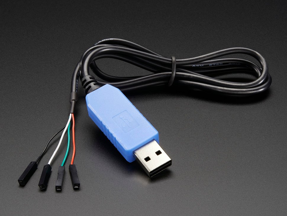
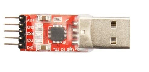
USB to Serial TTL (UART):
There are many options here. The one we recommend (for ease of use) is the Adafruit model:
- https://www.adafruit.com/product/954
- https://www.digikey.com/en/products/detail/adafruit-industries-llc/954/7064488
- https://www.amazon.com/dp/B00DJUHGHI/
Or you can search for "CP2102" and you'll get tons of hits from various brands/sellers that look like these:
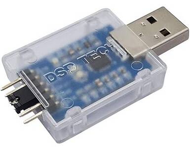
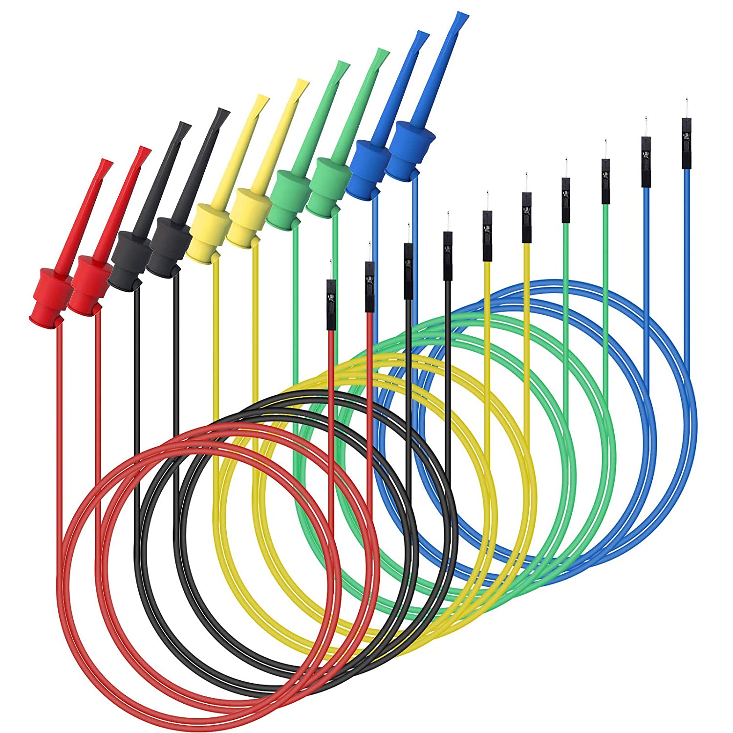
Mini-Grabbers to Male Jumper Wires
If you choose a different UART make sure that the wire-end of the mini-grabber can plug into the UART. So if you picked the red CP2102 UART, you will want the female mini-grabber.
Hardware Assembly:
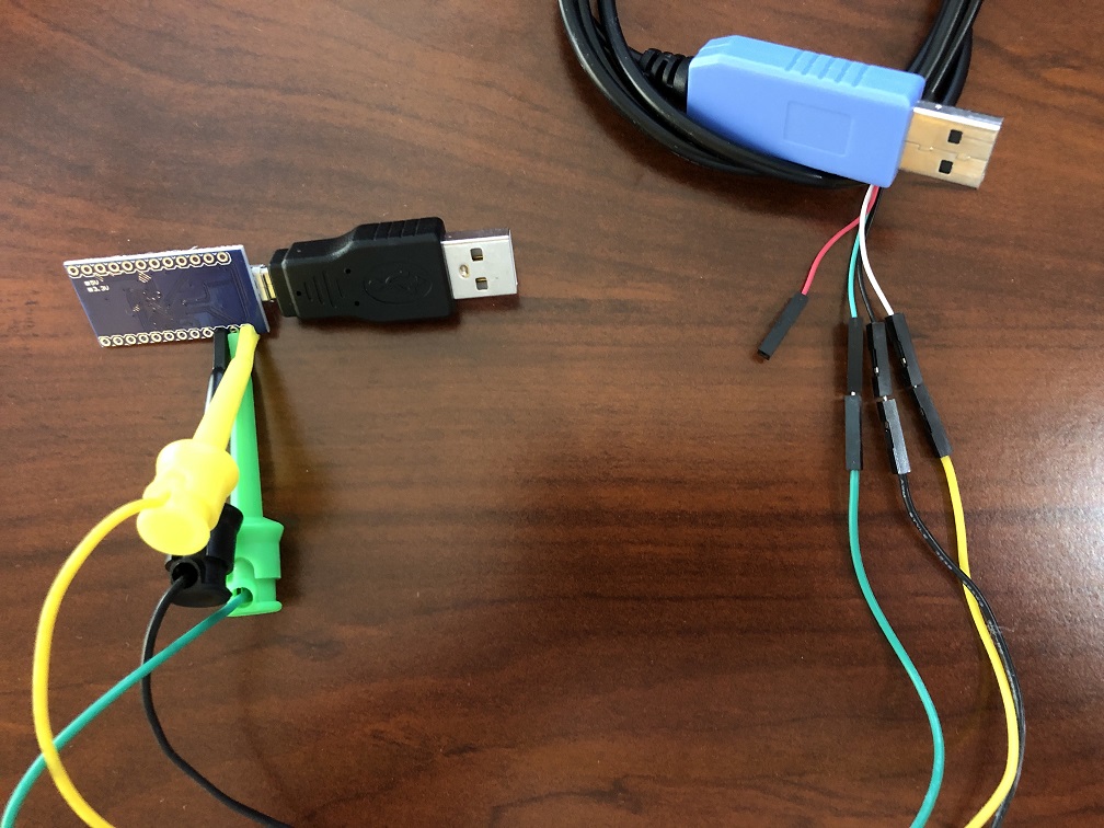
Step 1: Connect UART to the Pro Micro
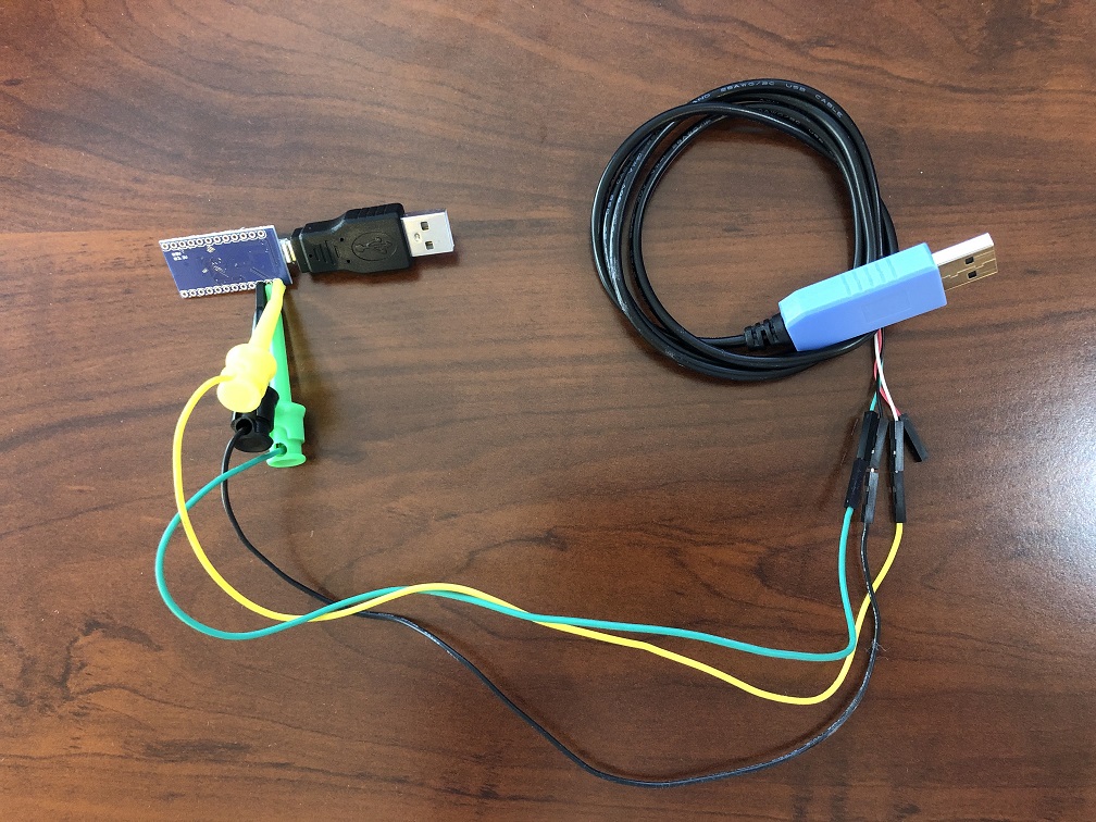
Once you have your hardware, you need to make some connections between your UART cables and the Pro Micro. Use the mini-grabber cables to connect them.
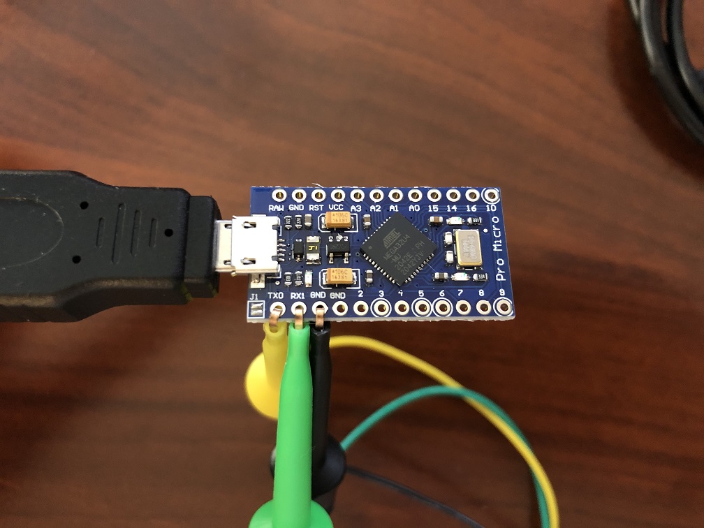
Make the following connections:
| UART pin | Microcontroller pin |
|---|---|
| TX | RX1 |
| RX | TX0 |
| GND | GND (any one is fine) |
| VCC | Leave unconnected |
Note that the mini grabber clips may not fit through the holes on the Pro Micro. This is fine.
Step 2: Download QMK Toolbox
A few QMK versions are known to work. e.g. 0.1.1, 0.2.2, and 0.3.1. Other versions may not work (e.g. 0.3.2 does not work).
Download QMK Toolbox. Ensure you download a version known to work. e.g. 0.3.1.
You want the file qmk_toolbox.exe. You'll find it under Assets, under the version number that you choose (e.g. 0.3.1).
Step 3: Flash PABotBase into your Device.
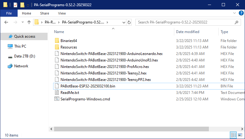
The root folder of the SerialPrograms package should have a set of .hex files for each of the different devices.
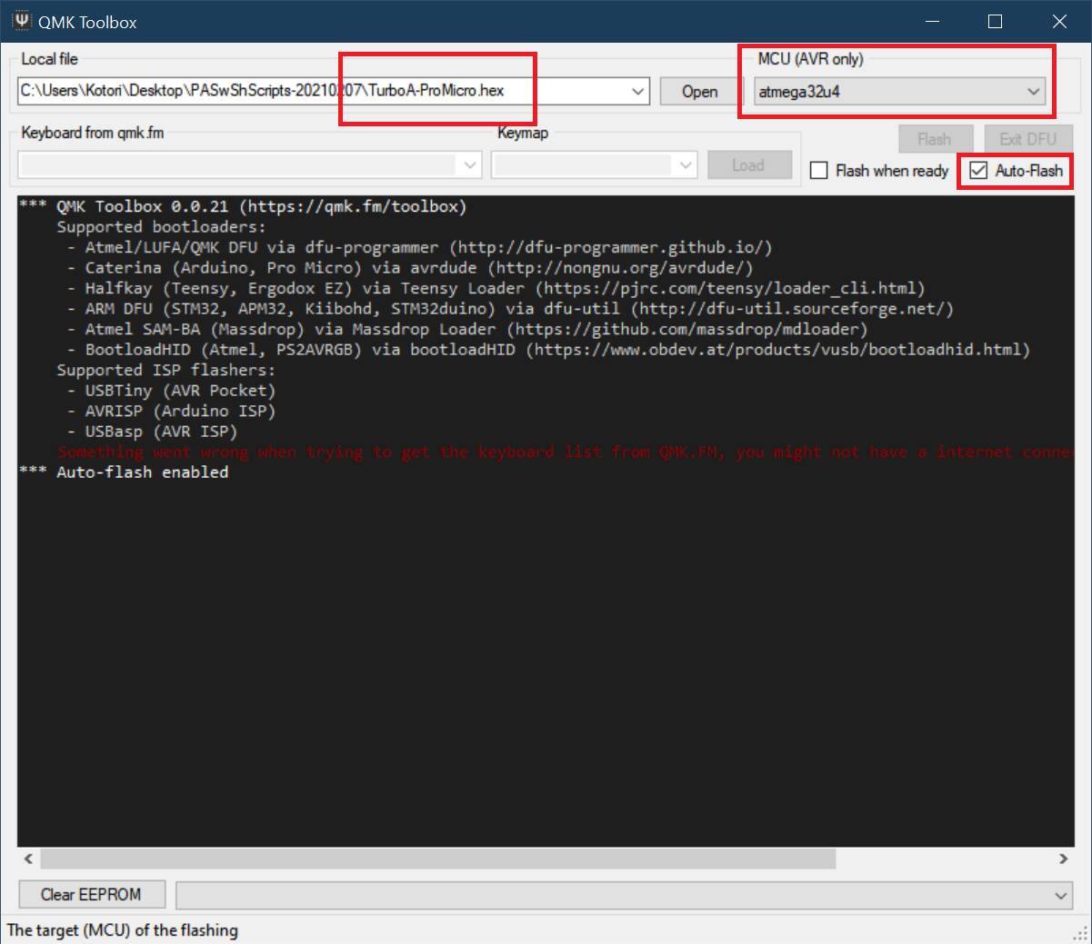
- Run the QMK Toolbox program that you downloaded in PART 2.
- Open the .hex named
PABotBase-NS-ProMicro-<version>.hex. - Change the MCU to
atmega32u4. -
Check the "Auto-Flash" box.
-
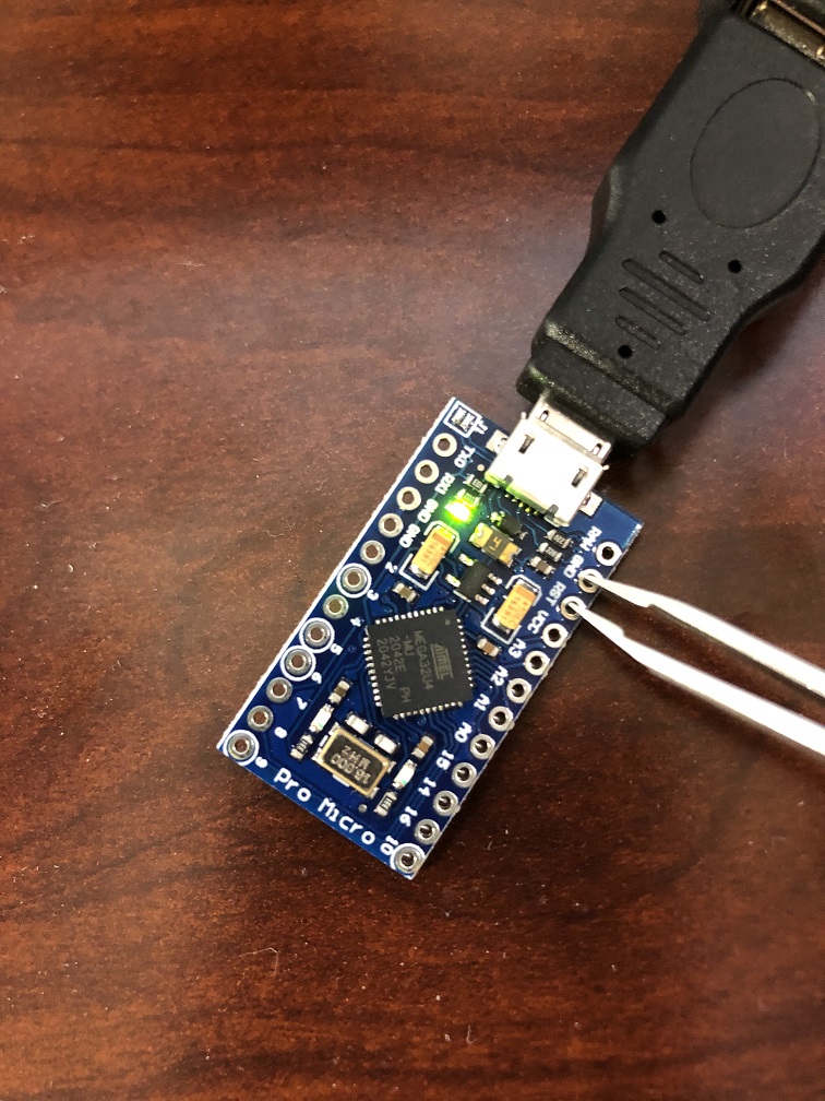
Plug the Pro Micro into your computer.
-
Short the RST and GND pins.
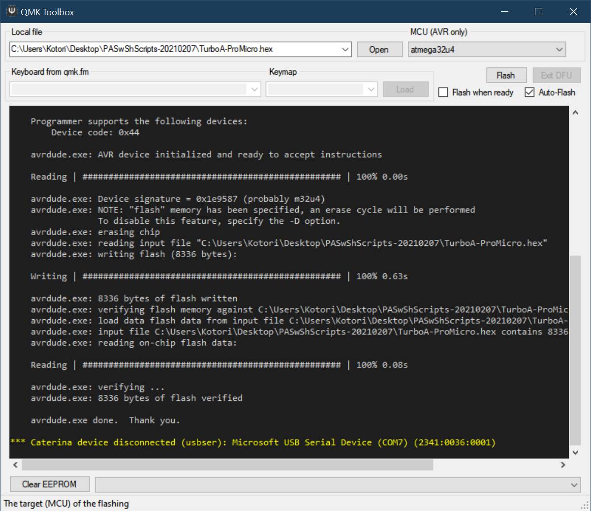
The QMK program will now flash the program to the Pro Micro and show a bunch of logging. Afterwards, the 2 LEDs on the Pro Micro should flash in unison for 5 seconds before turning off.
-
Unplug the Leonardo from your computer.
Step 4:
- Turn on your Switch and dock it.
- Connect your Pro Micro to the Switch's dock.
- Connect the UART to your computer.
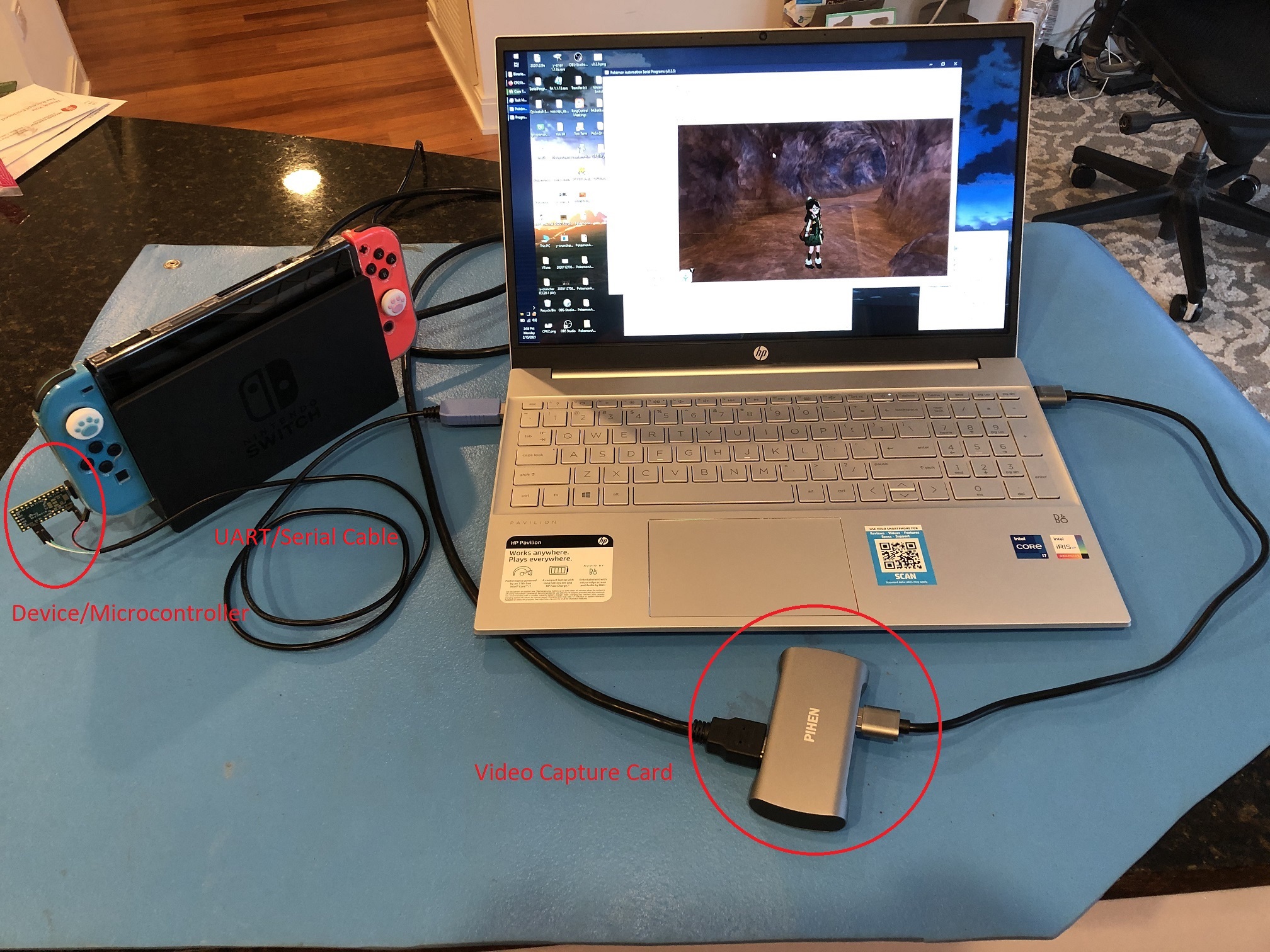
At this point, your final setup should look like this:
Software Setup:
Continue to: Wired Controller (AVR8) Software Setup.
Troubleshooting:
Docking and undocking the Switch resets or hangs the Pro Micro.
Main Article: Power Glitching
Credits:
- Kuroneko/Mysticial
- jw
Discord Server:
